What Is The Tension Control Of Slitting Machine
Body
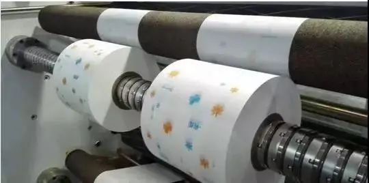
Tension control refers to the ability to control the tension of raw materials when they are transported on the equipment. The tension control of slitting machine must be effective for any running speed, including the acceleration speed, deceleration speed and uniform speed of the machine. Even in case of emergency shutdown, it shall be able to ensure that the cut raw materials are not scratched or damaged.

Why Tension Control Is ImportantIn The Slitting Machine
With the increasing degree of mechanization, the requirements for the efficiency of winding operation are also higher and higher. When the slitting machine is applied to the slitting operation of film, tape and paper, the large reel of the whole roll can be divided into several small reels according to different requirements to meet the needs of different occasions. The tension control system is the core part of the slitting machine.
The tension control of the slitting machine is basically manual tension control and automatic tension control. Manual tension control is to control the tension by adjusting the manual power supply device by the operator when the coil diameter changes to a certain stage during the winding or unwinding process.
Full-automatic tension control is to measure the actual tension value of the material belt directly by the tension sensor, and then convert the tension data into a tension signal and feed it back to the tension controller. By comparing this signal with the preset tension value of the controller, the control signal is calculated. The automatic control execution unit makes the actual tension value equal to the preset tension value, so as to achieve the purpose of stabilizing the tension.
The stability of tension control is directly related to the quality of slitting products. If the tension is insufficient, the raw material will loose or drift during operation, and the finished material will wrinkle after slitting and rewinding. If the tension is too large, the raw material is easy to be broken, resulting in more broken ends of the finished material after slitting and rewinding.
Tension Control Of The Slitting Machine
The formation of tension can be realized in many ways, but its basic principles are consistent. During the startup process, the linear speed of the winding coil is greater than the linear speed of the unwinding coil to generate a certain tension in the winding roll. When the winding reaches the appropriate tension required by us, timely adjust the power mechanism to stabilize the linear speed of the winding coil and the unwinding coil, so that the raw material can operate stably under this tension. The tension control system is to meet the tension stability of the whole machine.

Tension Control Detection System Of The Slitting Machine
1. Tension sensor detection
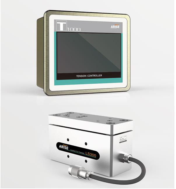
It is a direct detection of tension, which is closely combined with machinery, and is equipped with a detection method of moving parts. Usually two sensors are used in pairs, and they are installed on the end shafts on both sides of the detection guide roller. By detecting the applied load on both sides of the guide roller, the material belt makes the tension sensor sensitive element produce displacement or deformation, thus detecting the actual tension value, converting this tension data into a tension signal to feed back to the tension controller.

2. Indirect tension detection system of floating roll
A set of floating roll is installed in front of the tracking roll. The position of the floating roll is detected by a potentiometer. The tension control method is to maintain the constant tension by maintaining the position of the floating roll unchanged.
3. Magnetic particle clutch
Magnetic particle clutch is used to control the rotational torque of the input take-up roll to achieve tension control: the magnetic particle clutch is composed of the driving part and the driven part, and is connected with the take-up roll through the universal coupling and other transmission mechanisms, and the middle is filled with fine iron particles as the torque transmission medium.
A magnetic field is formed by applying a certain current to the excitation coil, and the magnetic particle is magnetized. The magnetized magnetic particles attract each other and form a chain arrangement. When the driving part rotates at a constant speed, the coupling force between the magnetic particles is destroyed and a circumferential tangential force is formed. The product of the tangential force and the radius of the magnetic particle circle is the rotational torque of the driven part for winding up, so as to realize the coupling of the output torque from the driving part to the driven part in continuous rotation, thus achieving the purpose of tension control.
4. The slitting & unwinding capacity and speed tension detection system
It mainly uses magnetic particle brake to control the unwinding speed. Its working principle is that the magnetic particle brake is equipped with a coupling, as well as input parts and output parts with magnetic coils. Below the magnetic coil is an annular groove, and below the groove is an annular rotor, namely the output part. The annular groove is located in the center of the output part, and the groove is filled with magnetic powder.
When there is excitation current in the magnetic coil, the coil will generate magnetic flux to make the magnetic particles arranged along the magnetic field direction, which will generate damping between the input part and the output part and transfer the torque. If the tension and speed applied on the aluminum foil are increased or decreased, the tension and speed can be effectively controlled by changing the magnitude of the excitation current, or the current or voltage value applied by the amplifier to the coupling coil.


Comments